Test Weight Separator Cylinder Replacement
Note: Before replacing the test weight separator cylinder, consult with a HarvestMaster Field Service Engineer.
This article explains how to replace a test weight separator cylinder.
Tools Required
-
5/16 wrench
-
5/32 Allen wrench
-
3/16 Allen wrench
-
Medium strength Loctite
-
Flathead screwdriver (small)
-
Feeler gauge set
Remove the Separator Cylinder
- Remove the load cell wire support socket cap screw with the 3/16 Allen wrench.
-
Remove the socket cap screws that attach the load cell to the support arm.
Be ready for the test weight chamber to drop down upon removing the load cell socket cap screw. Support the test weight chamber so it doesn't hang on the load cell and limit switch wires.
-
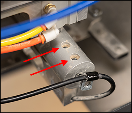
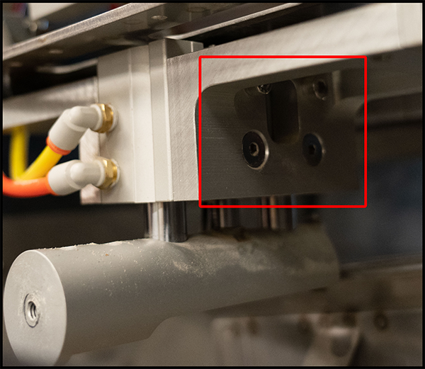
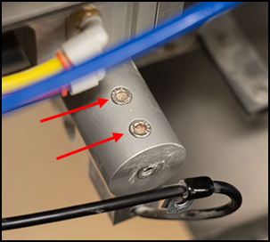
Remove the two socket cap screws on each side of the separator cylinder supports with the 3/16 Allen wrench.

-
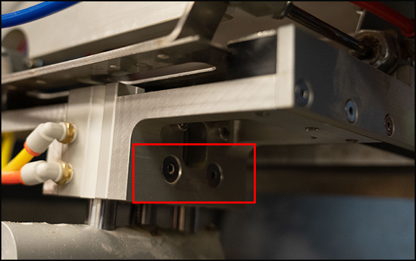
Remove the two countersunk Allen screws on each side of the separator cylinder with the 5/32 Allen wrench.
Note: The new version of this bracket does not include these two screws.
-
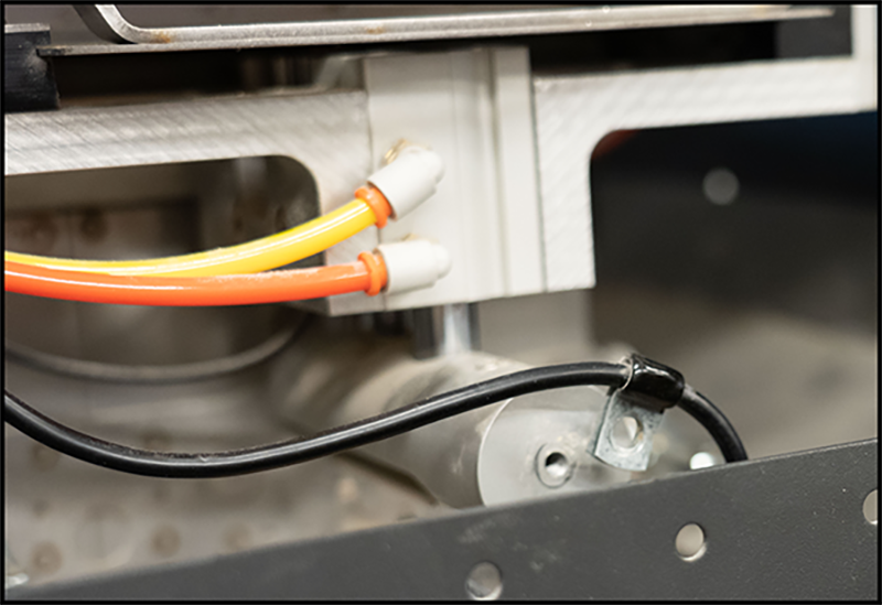
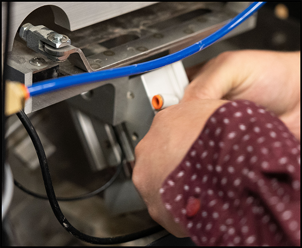
Detach the air hoses by compressing the orange collar and pulling the hose out.

-
Lower the separator cylinder down from the supports and loosen the limit switch sensor with the small flathead screwdriver. Extend the separator cylinder to fully release the sensor from the cylinder.

Note: Pay attention to the orientation of the limit switch sensor including which side the sensor is on and which channel the sensor is in.
Install the New Separator Cylinder
-
Turn on the GrainGage console.
-
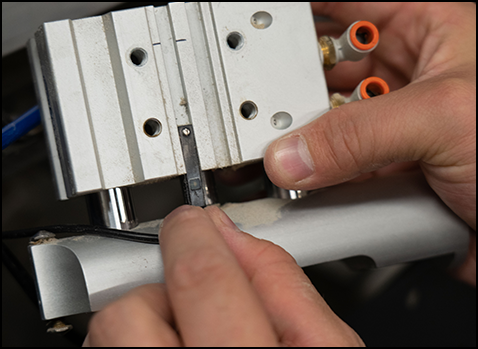
Extend the new separator cylinder and slide the limit switch into the channel.
-
Retract the separator cylinder.
With the GrainGage power on, the red LED will light up when sliding the sensor up and down in the channel. Put the sensor in the middle of the lit-up range and tighten securely with the small flathead screwdriver.

-
Apply medium strength Loctite to all four threaded holes on either side of the separator cylinder.
-
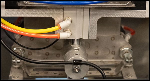
Raise the separator cylinder carefully between the support brackets from the bottom of the brackets up.
-
Replace the two socket cap screws on each side of the separator cylinder.
-
Replace the two countersunk Allen screws on each side of the separator cylinder.
Note: Tighten the countersunk Allen screws before tightening the socket cap screws, this will align the separator into place.
-
Apply medium strength Loctite to the two threaded holes in the top of the load cell and raise the test weight chamber back into place. This may take a little work to get into place on top of the overload protection screws in the load cell support arm.
-
Replace the two socket cap screws through the support arm into the load cell and tighten.
-
Apply medium strength Loctite to the threaded hole at the end of the load cell support arm.
-
Reattach the load cell wire support hanger with the socket cap screw.
-
Reattach the air hoses.
-
Adjust the overload protection screws with the 5/16 wrench with the feeler gauge to a .009 gap on the top overload screw followed by a .014 gap on the bottom overload screw by the load cell.
-
Verify the new separator cylinder operates smoothly.

If you need further assistance, contact the HarvestMaster Field Service Engineers. For contact information, see Contact a HarvestMaster Field Service Engineer.
- Phone Number: 435-753-1881
- Email: hmtechsupport@junipersys.com
- Address: 1132 W 1700 N, Logan, UT 84321

