Install Components
Most of the Cache Weigh System can be installed on your conveyor belt in the shop or field. You may prefer to weld the tone wheel to a wheel hub or bearing lock collar in a shop before beginning the rest of the installation. (See Change the Network Name.)
Install the Central Control Unit (CCU)
CCU Parts List
The following table lists the parts included with each CCU (Verizon PN 29358 or AT&T PN 28620) and CCU Mount Kit (PN 24854):
|
Central Control Unit and Mount Kit Parts |
|||
|
PN |
Qty |
Description |
Photo |
|
30123 |
1 |
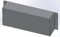
Central Control Unit |
|
|
29176 |
2 |
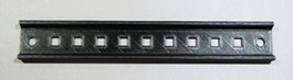
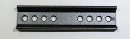
Junction Box Long Mount Channel |
|
|
29177 |
2 |
Junction Box Short Mount Channel |
|
|
29546 |
4 |
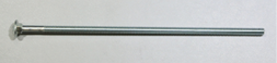
1/4”–20-7, Grade 2 Zinc Carriage Bolt |
|
|
5428 |
4 |
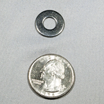
HRD 1/4” Washer, flat |
|
|
23132 |
4 |
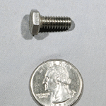
1/4”–20 x 5/8” SS Bolt (bars to CCU box) |
|
|
29147 |
4 |
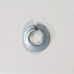
1/4” Lock washer, split (bars to CCU box) |
|
|
795 |
4 |
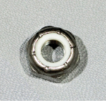
1/4”–20 Nylock Nut |
|
.png)
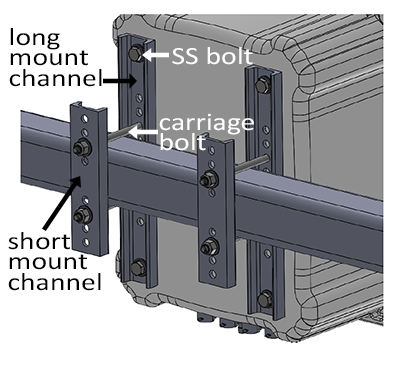
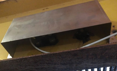
CCU and Mount Kit Diagram
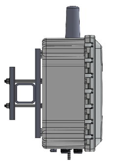
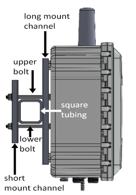
CCU Channel Mount Procedure
- Determine which holes on the junction box long mount channels (PN 29176) will best suit the CCU location and the size of tubing to which you are attaching the CCU.
- Insert the four carriage bolts through the appropriate holes in the long mount channels (two bolts per channel). The head of the bolt should be flush with the flat side of each mount channel.
- Use the four SS bolts (PN 23132) and the split lock washer (PN 29417) to attach the long mount channels to the back of the CCU. The flat side of the channel faces the back of the CCU box. The holes in the CCU box are threaded.
-
Hold the box in place so that the carriage bolts are above and below the square tubing to which you are mounting the box.
- Slide the short mount channels onto the carriage bolts to sandwich the tubing between the long mount channels and the short mount channels.
- Add a nylon nut (PN 795) and HRD washer (PN 5428) to the end of each bolt.
- Tighten into place.
- Cut off any excess bolt length.
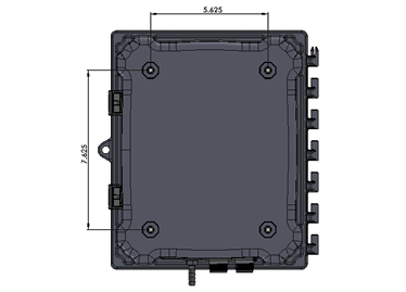
CCU Flat Mount Procedure
- Create a paper drill template using the dimensions shown.
- Find a flat surface that is solid and large enough to accommodate the CCU box.
If a flat surface cannot be found, create a mounting plate out of 10 gauge or heavier sheet metal. - Drill the four holes using a 5/16” bit. (The bit is slightly oversized.)
- Use the four SS bolts (PN 23132) and the split lock washer (PN 29417) to secure the CCU to the mounting plate so that it is level.
- Check that the CCU is level. Adjust the CCU to be level, if needed.
Install the Load Cells and Idler Wheels
Load Cell Mount Kit Parts List
The following table lists the parts included for mounting both load cells to idler wheels:
|
Load Cell Mount Kit Parts |
|||
|
PN |
Qty |
Description |
Photo |
|
32360 32356 |
2 |
Load Cell Mount Assembly Load Cell Mounting Kit |
|
|
24859 |
|
Idler Wheel Spacer |
|
|
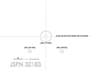
32183 |
1 |
Drill Template |
|
|
Loctite 243 |
|||
|
31359 |
1 |
Load Cell Cover |
|
|
29150 |
2 |
5/8”–11 x 3.5” Bolt through idler spacer |
|
|
2270 |
1/4”-20X 750 HX CAP G5 Bolt for load cell cover |
|
|
|
795 |
1/4”-20 Nylock Nut for load cell cover |
||


Install Load Cell and Idler Wheel
The following instructions describe how to mount a load cell and idler wheel. Repeat the process for the second load cell and idler wheel.
Use the load cell drill template (a paper that came with your Cache Weigh System) to mark the locations for drilling holes.
Once you have determined the idler wheels on which you will mount the load cells (see Plan for Load Cells (Weighing Idler Wheels)).
- Create room to reach under the chain to position the idler wheel, using one of the following methods.
- Remove the belted chain.
- Lift the chain off the idler wheels from above with a ratchet strap.
- Remove the idler wheel from the conveyor.
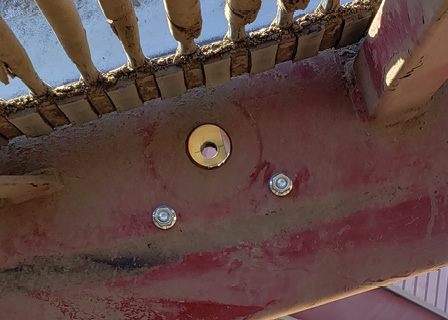
- Mark a straight line between the two adjacent idler wheel bolts. (Use a marker or a long piece of masking tape.)
- Position the template to align the printed center line with the marked line. Hold the template in place with masking tape.
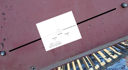
- Mark the center two 3/8” holes on the template using a center punch.
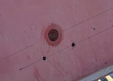
- Expand the size of the original idler wheel axle hole to 1.25” or slightly larger to accommodate the weighing idler wheel axle and spacer. Center the new hole over the old hole.
![]() CAUTION: The idler wheel shaft needs to be able to float in this hole.
CAUTION: The idler wheel shaft needs to be able to float in this hole.
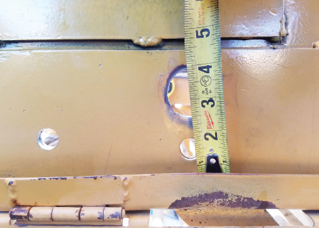
- Drill the two 3/8” holes using a 3/8” drill bit.
- Remove the two nuts from the load cell assembly.
- Align the assembly so that bolts go through the two 3/8” holes. Slide the bolts into the 3/8” holes you drilled in the conveyor belt frame.
- From the inside of the piler, secure the nuts finger tight.
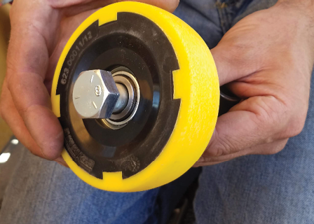
- Slide the 5/8”–11 x 3.5” bolt through the idler wheel.
Note: One side of the wheel has a small collar that extends perpendicularly from the center hole. Position the bolt head on the flat hub side of the wheel.
- Slide the idler wheel spacer onto the bolt.
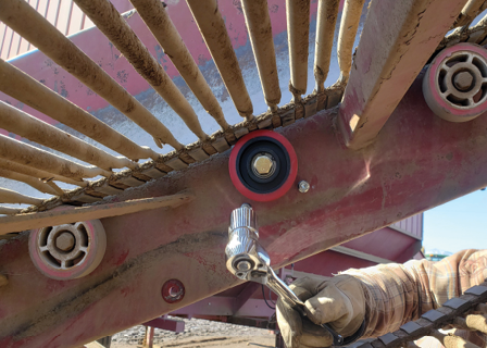
- Apply Loctite 243 to the idler wheel axle hex bolt.
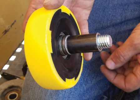
- From the inside of the piler railing, position the bolt in the enlarged hole and thread the bolt into the load cell and tighten.
Fine Tune Alignment
- Measure the angle of the piler frame.
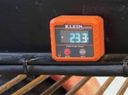
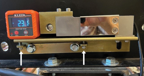
- Use the small screws to adjust the load cell to be the same angle as the piler frame.
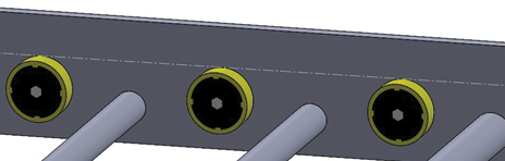
- Remove the piler belt (or come from underneath) and place a straight edge (a 4 ft level works well) on the piler rollers such that it rests on the load cell idler wheel and one idler wheel on each side.
- Assess the relative height of the load cell idler wheel. All three idler wheels must be perfectly level. Use the two small screws on the load cell to move the wheel up or down into alignment.
Tip: Move the load cell idler wheel slightly above the above the needed height. It will settle into the correct height more easily than if you try to nudge it up to the correct height.
- Verify that the angle of the piler frame and the angle of the load cell is the same. Adjust as necessary using the small screws.
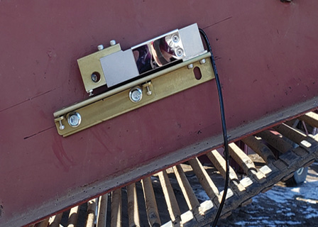
Complete Load Cell Installation
- Tighten the two load cell mounting bolts.
- Using UV resistant wire ties, carefully tie the sensor wires from the weighing idler wheel load cells to an anchor position located within one to three inches of the load cell. Position the ties so that no force (up or down) is applied to the load cell.
- Route the load cell wire to the CCU, tying it with UV resistant wire ties at appropriate intervals to protect the cable and keep it safely out of the way.
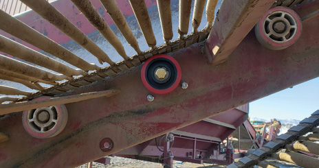
- Install the Load Cell Cover with the open side down.
- Position the shade so that it covers the sensor as much as possible without touching it.
- Determine which two holes in the cover to use to mount it to the convey belt frame. Select the two holes that will prevent the cover bolts from rubbing on the conveyor belt.
- Drill mounting holes into the conveyor frame using the load cell cover itself as a drill template.
- Thread the bolts through the frame and the cover from the conveyor side, so that the nut is installed on the outside of the conveyor system.
- Secure tightly with the provided nuts.
- Install the second idler wheel on the other side using the instructions outlined above.
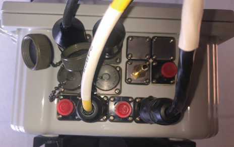
- Plug the load cell cables into the port A (Load cell A) and B (Load cell B) of the CCU. To determine right and left, look directly at the conveyor as the crop would flow away from you.
Note: If you have multiple systems, always identify the right and left the same way.Note: Enter the number on the end of the cables into the Cache Weigh System. (See Connect Tablet to Cache Weigh System.)
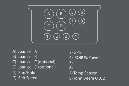
- Plug the right-side load cell cable into Connector B of the CCU.
- Plug the left-side load cell cable into Connector A of the CCU.
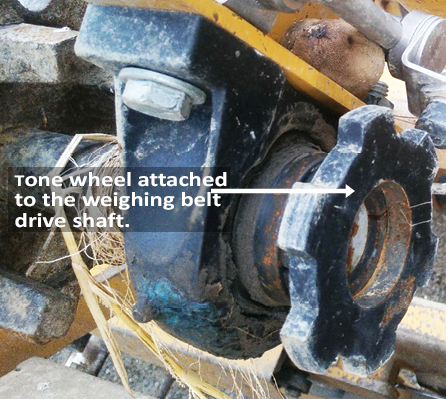
Install the Belt Speed/RPM Sensor
The belt speed sensor consists of a proximity sensor mounted with two 360° mounting systems, a 200 mm rod, and a tone wheel. The belt speed sensor can be installed in many different ways. Find the best fit for your conveyor belt.
Belt Speed Sensor Mount Kit and Parts List
The following table lists the parts included for mounting the belt speed sensor:
|
Belt Speed Sensor Mount Kit Parts |
|||
|
PN |
Qty |
Description |
Photo |
|
24871 |
2 |
Proximity Sensor 360° Mount |
|
|
24872 |
1 |
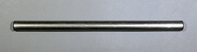
Proximity Sensor Rod, 12 mm x 200 mm |
|
|
24855 |
1 |
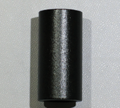
Tone Wheel |
|
|
24881 |
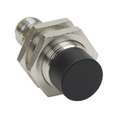
1 |
Inductive Proximity Sensor |
|
|
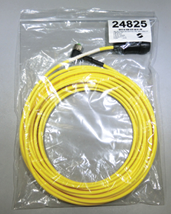
24825 |
Proximity Sensor Cable (10m) |
|
|
|
NA |
1 |
Weld Hub or Lock Collar* |
|
|
29148 |
1 |
5/8” Split Lock Washer for nut side |
|
|
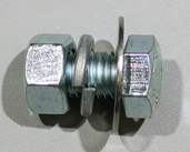
29152 |
1 |
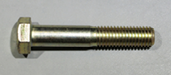
5/8”–11 x 1” Hex Bolt |
|
|
29153 |
1 |
5/8” Washer for conveyor belt side |
|
|
29154 |
1 |
5/8”–11 Nut |
|

* The weld hub or lock collar must fit your drive shaft. Purchase a standard W-Series weld hub or lock collar with a bore hole that fits the diameter of your conveyor belt’s drive shaft. An industry-standard W-series weld hub with the following dimensions can be purchased at most parts stores.
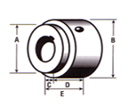
- 1 5/8” (the tone wheel ID drops over this shoulder to be welded)
- 1 13/16”
- 7/16”
- 1”
- 1 7/16”
Note: If the belt drive shaft is larger than 1 5/8”, the hole in the tone may need to be cut larger to fit over the shaft.
Belt Speed Sensor Installation Instructions
Once you have determined the placement for the tone wheel and proximity sensor (see Plan for Tone Wheel and Speed Sensor),
![]() CAUTION: The tone wheel spins anytime the belt is moving. It could catch on loose clothing, hair, etc. Install the tone wheel in a safe location or build a safety shield to prevent injury.
CAUTION: The tone wheel spins anytime the belt is moving. It could catch on loose clothing, hair, etc. Install the tone wheel in a safe location or build a safety shield to prevent injury.
- Spot weld the tone wheel and the weld hub in at least three spots.

- Slide the tone wheel/weld hub onto the weighing belt drive shaft. Turn the set screw on the hub to secure it in place.
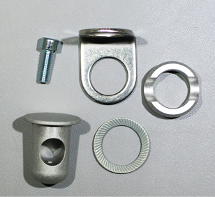
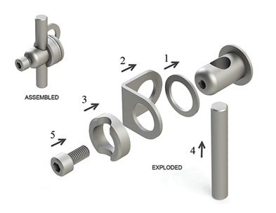
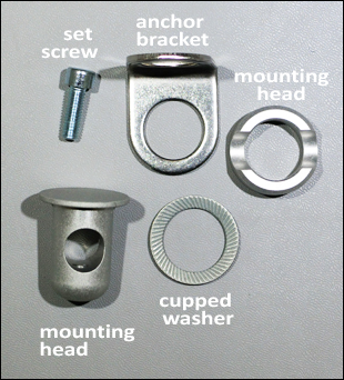
- Lay out the parts of the speed sensor mounting systems (PN 24853) according to the illustration.
- Locate a position for the L-shaped bracket of the mounting system where the proximity sensor will be within 1/4” of the tone wheel teeth. You can attach the anchor bracket to an existing bolt on the conveyor belt.
Anchor bracket placement 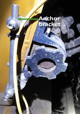
- If needed mark and drill a 5/8” hole in the side of the conveyor belt for the anchor bracket.
- Assemble one mounting system. (See illustration in step 3.)
- Slide the mounting head through the cupped washer and the anchor bracket, from the inside to the outside. The cupped washer rests between the mounting head and the anchor bracket.
- Insert a 5/8” bolt through the hole you drilled in the conveyor frame.
- Place the empty hole of the anchor bracket on the bolt. Secure loosely with 5/8” washer and 5/8” nut. Leave enough give to allow the anchor bracket to rotate for final positioning of the rod and sensor.
- Slide the mounting plate onto the mounting head, rotating them so that the plate grooves line up with the holes in the head.
- Insert the proximity sensor rod through the mounting head. Leave one end near the tone wheel.
- Insert the set screw into the mounting head. Tighten the screw to hold the rod in place.
An assembled mounting system is pictured below:
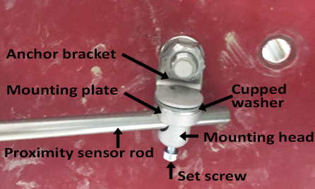
- Slide the mounting head through the cupped washer and the anchor bracket, from the inside to the outside. The cupped washer rests between the mounting head and the anchor bracket.
- Assemble the second mounting system.
- Slide the mounting head through the cupped washer and the anchor bracket, from the inside to the outside.
Note: This must be done before the sensor is mounted to the bracket. - Slide the mounting plate onto the mounting head, rotating them so that the plate grooves line up with the holes in the head.
- Slide the assembled mounting system parts onto the empty end of the proximity sensor rod.
- Insert the set screw. Tighten the set screw.
- Slide the mounting head through the cupped washer and the anchor bracket, from the inside to the outside.
- Remove one of the nuts from the proximity sensor.
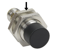
- Insert the proximity sensor through the second hole of the anchor bracket with the sensor’s face pointing out and away from the bracket. Replace the nut to secure the proximity sensor to the anchor bracket.
- Rotate the rod until the face of the proximity sensor is perpendicular to and 1/4” from the teeth of the tone wheel.
Note: To adjust the proximity sensor’s distance from the tone wheel, move the rod or adjust the lock nuts on the proximity sensor. - Tighten the set screws at either end of the rod and the nut anchoring the mount.
- Connect the proximity sensor cable to the proximity sensor, using the right-angle connector on the cable.
- Tighten the threaded collar of connector for the proximity sensor cable right-angle.
- Route the proximity sensor cable toward the CCU so that it will be safe from harm. Secure the cable with UV resistant zip ties to relieve stress on the cable coming from the right-angle connector.
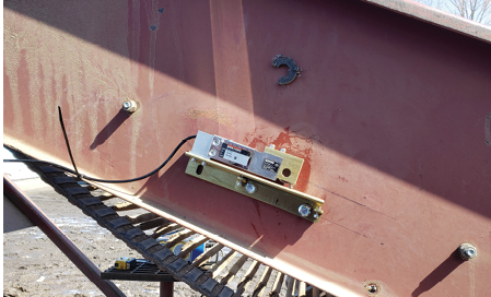
A completed installation of the belt speed sensor is pictured below:
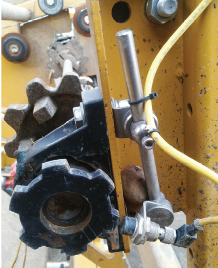
- In an out-of-the-way place between the belt speed sensor and the CCU, neatly coil and zip tie any extra cable.
- Plug the bulkhead end of the cable into Position 2 (Belt Speed) of the CCU.
- Inspect the sensor cable run to ensure that it is secure and protected.