Plan for Component Replacement
Most Cache Weigh System installations will be unique in some aspect. The following best practices for planning and installing the Cache Weigh System apply to conveyor belts that conform to the system requirements. (See System Requirements.) Following these best practices, regardless of your customizations, will create a secure, accessible, and durable Cache Weigh System.
![]() CAUTION: Plan your Cache Weigh System layout before you begin installation. Lack of planning may result in a system failure or a system that is less accurate or serviceable than desired.
CAUTION: Plan your Cache Weigh System layout before you begin installation. Lack of planning may result in a system failure or a system that is less accurate or serviceable than desired.
Before you install any part of the Cache System, inspect the conveyor belt and identify locations for each of the components listed below. As you identify those locations, consider the following:
- Is the location accessible for maintenance?
- What cables or wiring will need to access this part? Is there a clear, secure path for the wiring?
- Would replacing the part be convenient?
|
Considerations for Placement of Each Component |
|
|
Component |
Part Specific Placement Considerations |
|
Central Control Unit |
Must connect by wire to all other system components, except the tablet. |
|
Power Cable |
Connect to 12-16V DC power. If this is not available, a converter may be necessary. |
|
Cables |
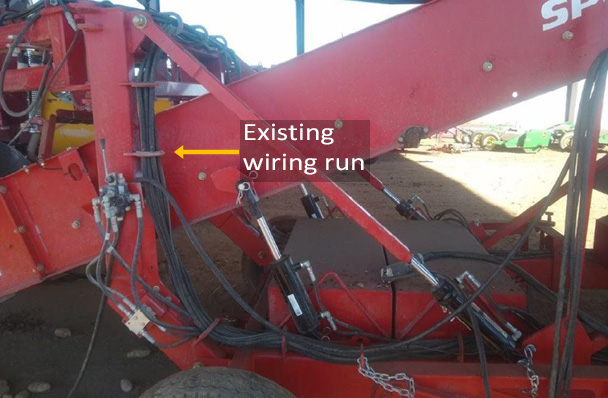
Create a clear, secure path. Use existing wiring runs. |
|
Load Cell (x2) |
Mount on idler wheels to create idle weighing wheels. Replace worn wheels. |
|
Tone Wheel |
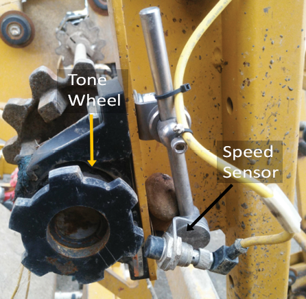
Install on the conveyor’s weighing belt drive shaft. |
|
Speed Sensor |
Mount 1/4” from the teeth of the tone wheel. |
|
Tablet |
Position for convenience and desired portability. |
Additional detailed guidelines for determining the optimal placement for each part in the Cache Weigh System installation follow.
Plan for Central Control Unit (CCU)
As the hub of the Cache Weigh System, the CCU must connect to all other components of the system.
.png)
Place the CCU according to the following guidelines.
- Place the CCU close to the midpoint between the load cells and speed sensor.
- Mount the CCU vertically so that it is horizontal with the ground. Cables plug in from the bottom.
- Mount the CCU to the conveyor belt’s square tubing.
Note: The CCU can also be mounted to a flat surface. - Allow sufficient space beneath the CCU to accommodate the sensor wire bulkhead connectors to plug in.
Plan Wiring and Cable Runs
Placing the necessary wiring in existing wiring runs is the best way to create a clear, secure path.

To determine the best placement for wiring, ask:
- Are there existing wiring runs between the component and the CCU?
If not,
- Is there another route for this cable that is safe, secure, and serviceable?
- Will this wiring route create a tripping or interference hazard?
- Are there any potential pinch points in this wiring route?
- Is this cable accessible if it needs to be changed?
- Is this cable long enough to reach the CCU via the chosen route? The Cache Weigh System includes a 20-foot load cell cable and a 32.8-foot speed sensor cable.
- If the provided cable isn’t long enough, is there a more efficient path?
- Is 12–16V DC power available for the CCU? If not, where is the best place to find 110V AC (i.e. to power the AC to DC converter)
- Will moving parts interfere with the cable?
Note: Avoid placing any wire where it could be caught by moving parts. - Is there a convenient, safe place to coil and tie up excess cable?
Note: Cables that are too long should always be coiled and tied up out of the way. Never cut long cables.
Plan for Load Cells (Weighing Idler Wheels)
Mounting a load cell onto an idler wheel creates a weighing idler wheel. Position the two weighing idler wheels
- Directly across from each other.
- About 1/4 of the way up on the angled portion of the piler or 1/4 of the way from the start of a flat conveyor and at least two idler wheel positions from the bottom of the piler.
- At least two idler wheel positions from the crop entry point.
- On a straight section of the conveyor belt. Each weighing idler wheel must sit between two other idler wheels. All three wheels must be in perfect linear alignment. The conveyor belt must have continuous contact with all three idler wheels.
- As far from the belt drive shaft as possible (still maintaining at least two positions away from the end of the belt and the crop entry point).
Plan for Tone Wheel and Speed Sensor
The tone wheel is installed on the conveyor’s weighing belt drive shaft The speed sensor is mounted 1/4” from the teeth of the tone wheel as seen below.

![]() CAUTION: The tone wheel spins when the belt moves. The wheel could catch on loose clothing, hair, etc. Install the tone wheel in a safe location or build a safety shield to prevent injury.
CAUTION: The tone wheel spins when the belt moves. The wheel could catch on loose clothing, hair, etc. Install the tone wheel in a safe location or build a safety shield to prevent injury.
Plan for Tablet
To determine where you will place your tablet, consider
- Will you mount the tablet?
A mount for your rugged tablet is convenient and allows the tablet to be easily removed. If you use a HarvestMaster tablet, HarvestMaster can provide mounting equipment that is ideal for the environment. - How will you power the tablet?
- Option 1—Charge the tablet independently of the piler.
While some tablets are rugged enough to be connected to power at the piler, many do not have sufficient protection against dust to power the tablet safely and reliably at the piler. Charge these tablets in a dust free area at the end of your workday.
- Option 2—Connect a charge cable to the piler.
While most pilers have a 12-volt output that can be used for charging a tablet, we recommended caution in using this option. The warranty of many tablets may be void if using a method for charging that is not using a typical wall outlet. Also, the charging port on many tablets are not rated for the type of dust that would be introduced by charging in this environment.
If you choose to charge your tablet from the piler, use a DC converter that converts 12V to 5V USB output. These can terminate with a female USB connection for easy connection to a tablet charging cable.
- Option 1—Charge the tablet independently of the piler.