Create the AB Line
You can use the GNSS receiver to provide real world reference locations for Mirus to use in creating the map of your field. Mirus creates a map based on a reference line called the AB Line. Follow the steps below to create an AB Line that corresponds to one side of your physical field.
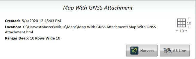
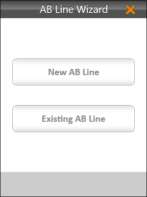
On the Maps screen,
Note: If you want to edit an existing line, select Existing AB Line and then select the map file that contains the AB Line you want to copy.
- Set the plot dimensions.
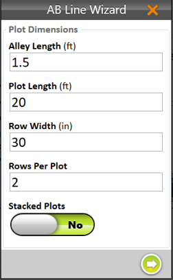
- Alley Length—The alley is the empty space between ranges.
Note: The minimum Alley Length is 0.1 ft, which creates a field with no alley. - Plot Length—The length of the space allotted for the plants to grow.
- Row Width—The width of the space allotted for each row of plants to grow.
- Rows Per Plot—The number of plant rows to be grouped together to create a plot.
Note: The row width and rows per plot should equal the effective swath width. - Stacked Plots—A group of plots separated from other plot groups by a larger alley. This option defines a longer alley after a specific number of smaller alleys between plots. If you are using stacked plots, turn on Stacked Plots and define the number of plots per stack and the stack alley width.
- Alley Length—The alley is the empty space between ranges.
- Tap the next arrow
 .
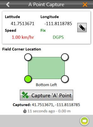
. - Move your GNSS receiver to the location you want displayed in Mirus as the lower left corner of the field. When using the GNSS attachment with a GrainGage and the correct offsets entered, position your combine in front of the first plot with the first plant contacting the cutter bar or deck plates.
- In Mirus, tap Capture ‘A’ Point.
Note: You can manually edit the latitude and longitude of the ‘A’ point before capturing it.
- Tap the next arrow .
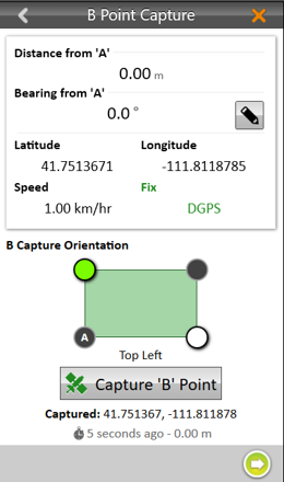
- Move your GNSS receiver to the location you want displayed in Mirus as the upper left corner of the field. For example, position your combine, pointing the same direction, at the end of the first row of the first plot with the last plant touching the cutter bar or deck plates.
Note: If it is not feasible to drive exactly along your row as you would to harvest, you can drive the combine parallel to your row to the side of the plot, and then reset the corner(s) using an offset distance in Mirus once the AB Line has been created.
- To improve the accuracy of the map with the AB Line you are defining,
- Drive the entire length of the field between capturing the ‘A’ and ‘B’ points.
- Use the pencil button to enter the distance from your first corner A and the bearing in degrees from A to B.
- In Mirus tap Capture ‘B’ Point.
- Tap the next arrow .
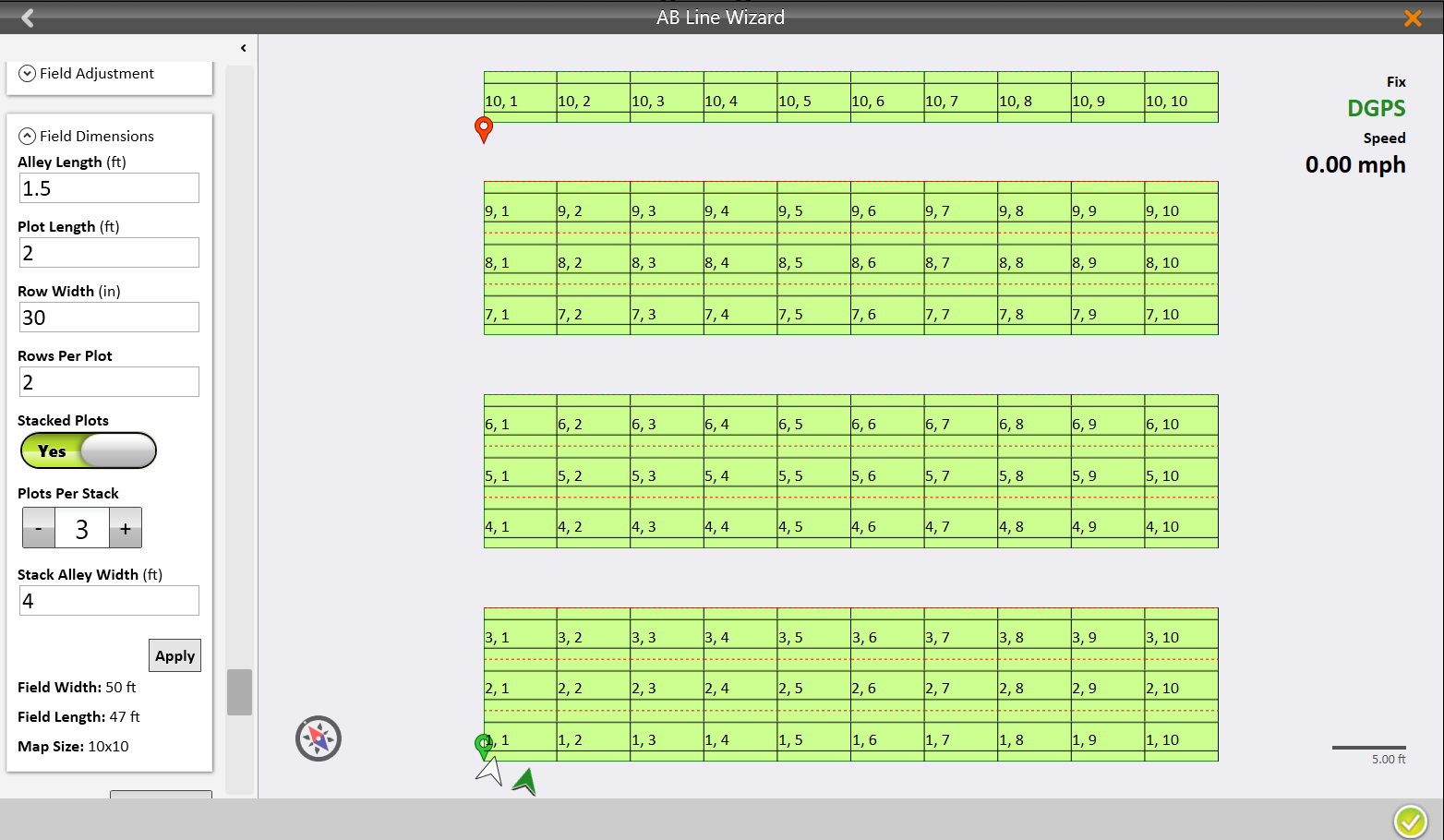
Mirus will display the Map View of the field calculated from the AB Line.
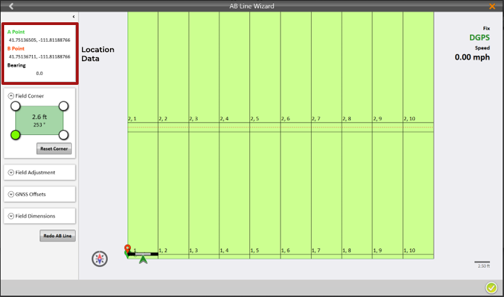
All of the field parameters are displayed on the left side of the screen. Several of them can be edited from there.
| AB Line Wizard Final Screen | |
| Setting | Description and Options |
|
A Point B Point Bearing |
View the A and B coordinates and the bearing entered. |
| Field Corner | Reset the corner to re-position the AB line based on your new position. |
| Field Adjustment | Change the vertical or horizontal width of your field. |
| GNSS Offsets | View the currently set offsets. To change them, use the directions in Adjust the GNSS Settings. |
| Field Dimensions | Adjust the Alley Length, Plot Length, Row Width, Rows Per Plot, and choose Stacked Plots. |
| Redo AB Line | Recapture the AB Line. |
The following Map View shows a field of stacked plots where groups of three plots are separated by a 4-foot stack alley. Within each group, the three plots are separated by 1.5 foot wide alleys.